
OutPut Devices |
|||||
In this assignment, I am going to interface a 5V Relay module with Arduino Uno to control high power devices. As we already know, Arduino Uno work on 5V and the maximum current a digital pin can drive is less than 40mA. In this assignment I am using a 5V channel relay module for driving higher power devices like home appliances DIRECTLY with Arduino depending on the use case we can go with 2 channel relay, 4 channel relay, 8 channel relay…... |
|||||
|
|||||
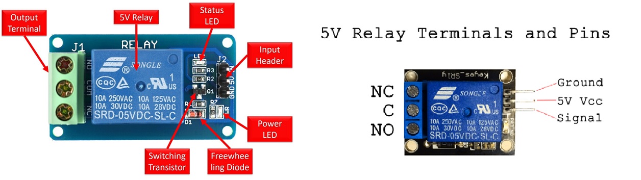
Relay ModuleA relay is generally an electrically operated switch. The principle used by the relays is an electromagnet to mechanically operate the switch. So basically it operates a switch using an electromagnet which needs only less power like 5V, 12V or 24V. Different kinds of relays are available in the market like SPDT, DPDT, SPST, 5V, 12V, 24V and with various high current/voltage driving capacity. |
|||||
Relay has two groups of Pins: Low voltage group and High voltage group. - Pins in the Low voltage group are connected to Arduino, including three pins: - Pins in the high voltage group are connected to the high voltage device, including three pins (usually in screw terminal):
|
|||||
Things to note when working with your Relay* The relay is not an ideal switch...meaning don't use your relay for basic switching purpose like turning on/off LED...it will wear off the mechanical parts faster...this example was just for demonstration |
|||||
 |
|||||
Controlling DC Devices with Relay
|
|||||
NO, NC and COM TerminalsUsually SPDT (Singe Pole Double Throw) relays have 3 output terminals, these are the 3 terminals of internal SPDT electromagnetic switch. Common (COM)This is the commonly terminal. This terminal will be connected to either of other 2 terminals (NO or NC) based on the state of relay. Normally Open (NO)As the name indicates this is normally open terminal, ie. if the relay is not energized (not ON), this pin will be open. We can say that the switch is OFF by default and when the relay is energized it will become ON. Normally Closed (NC)As the name indicates it is normally closed terminal, ie. if the relay is not energized (not ON), this pin will be closed. We can say that the switch is ON by default and when the relay is energized it will become OFF. |
|||||
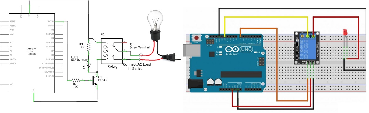
Interfacing Relay with Arduino UnoIn the first phase I am going to control a normal LED for testing the functionality of the relay as playing directly with AC needs to be very careful. |
|||||
Controlling DC Devices using Arduino Relay Module |
|||||
Circuit Diagram and Explanation |
|||||
 |
|||||
Description
|
|||||
 |
|||||
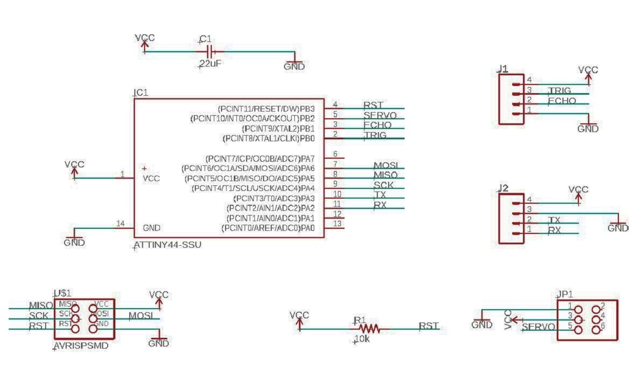
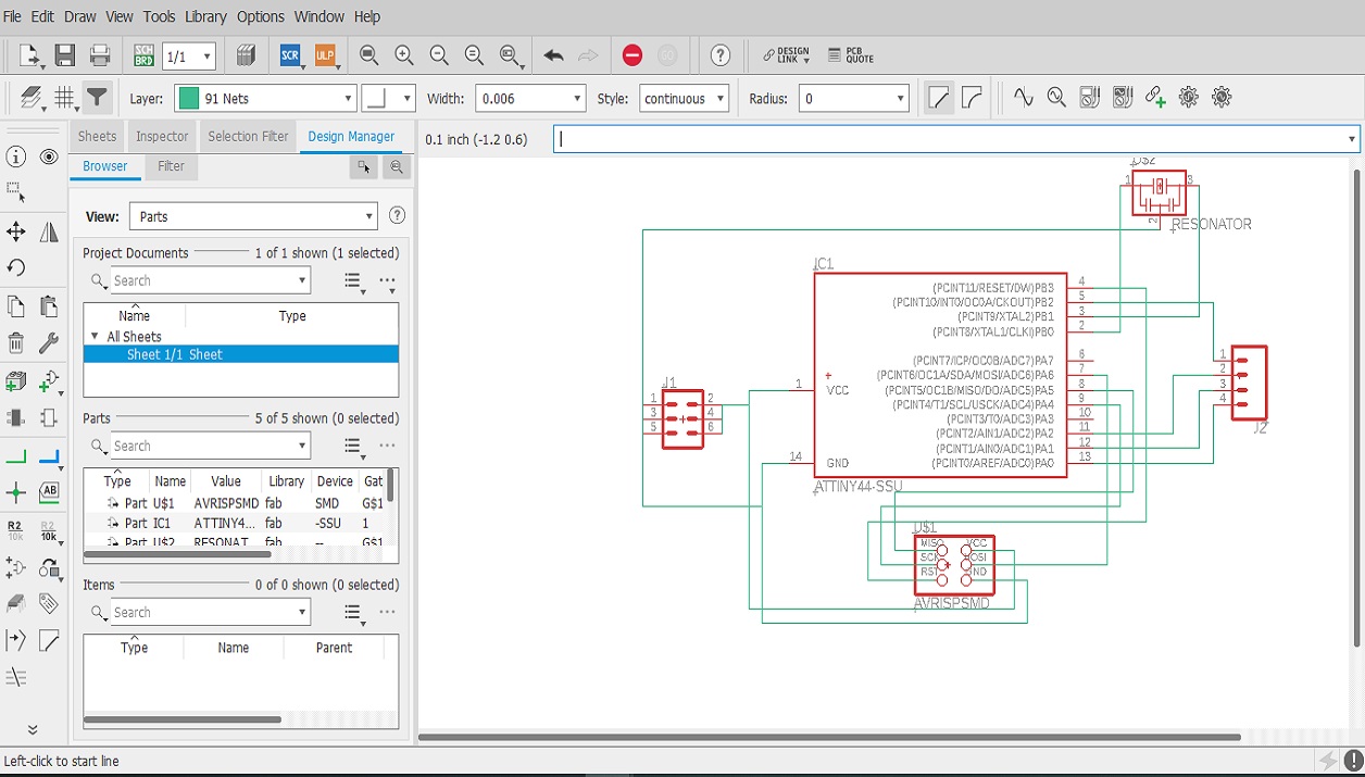
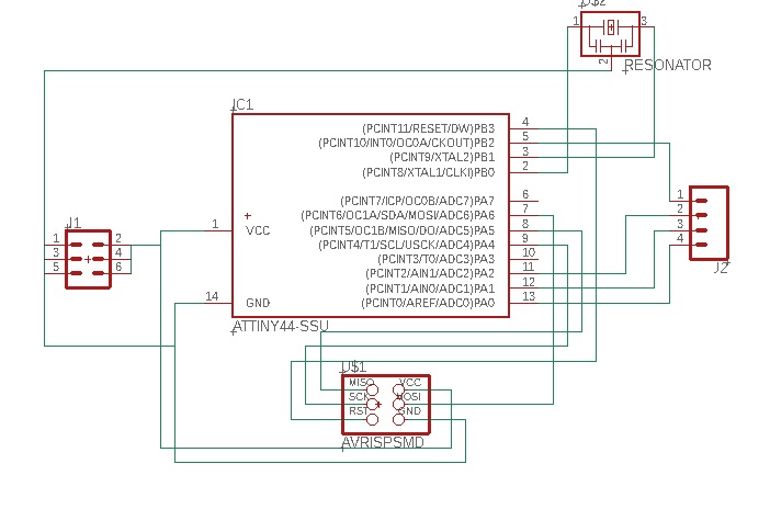
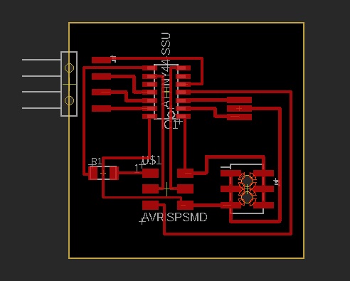
Board Design |
|||||
 |
|||||
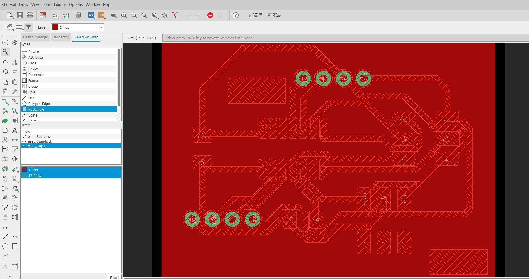
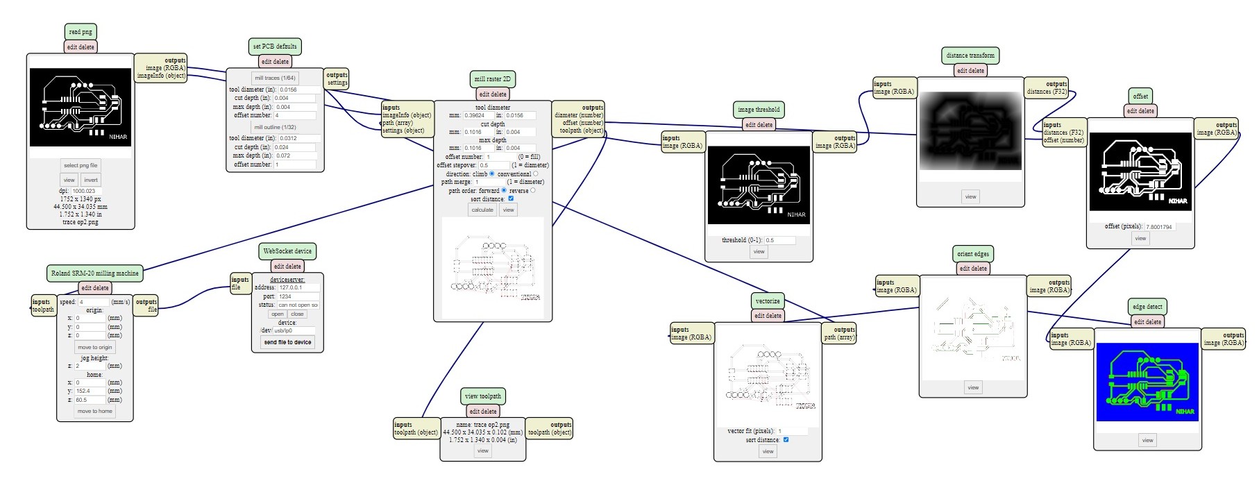
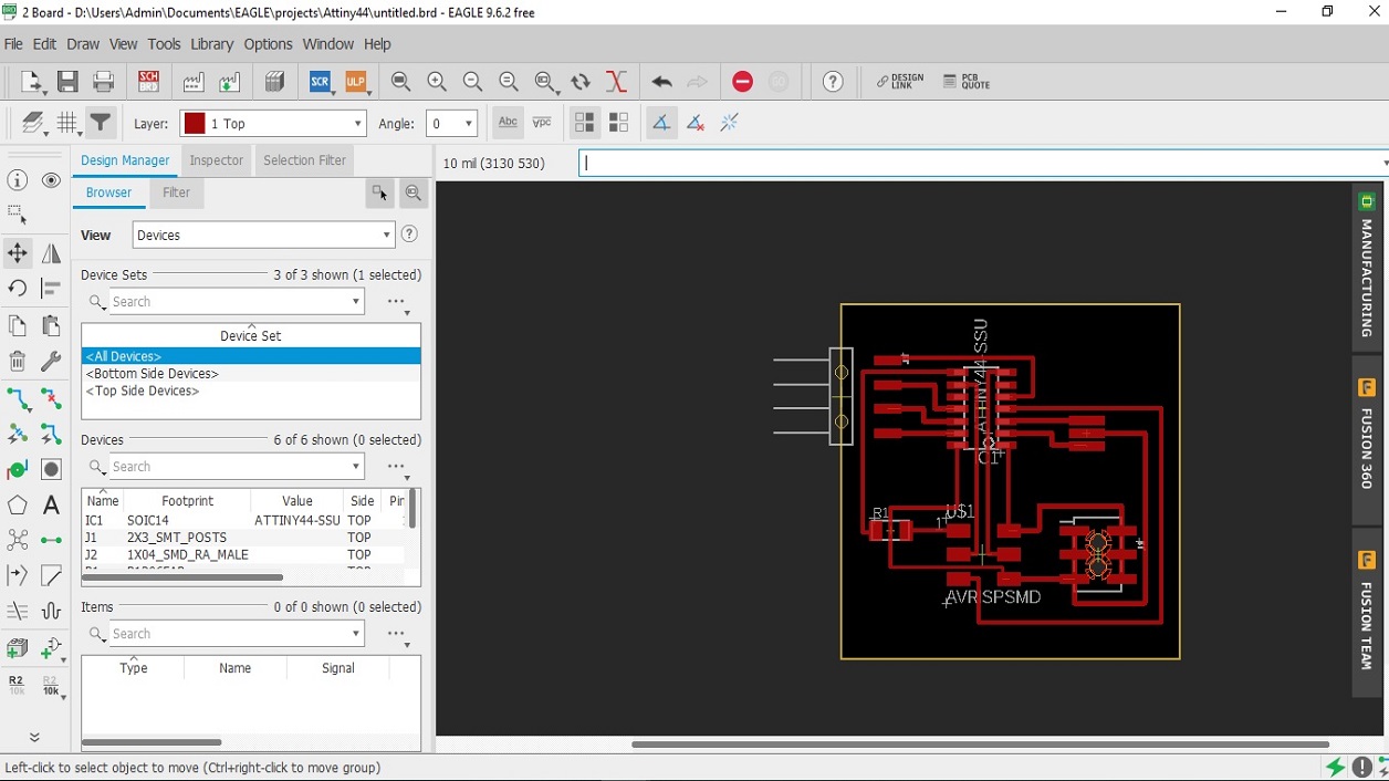
After that I started drawing the board for milling and soldering the components. The designed circuit for milling of the PCB is as shown below: |
|||||
 |
|||||
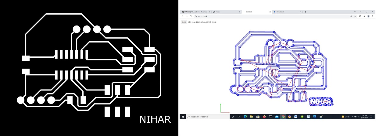
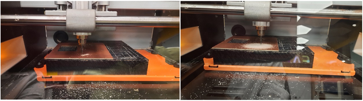
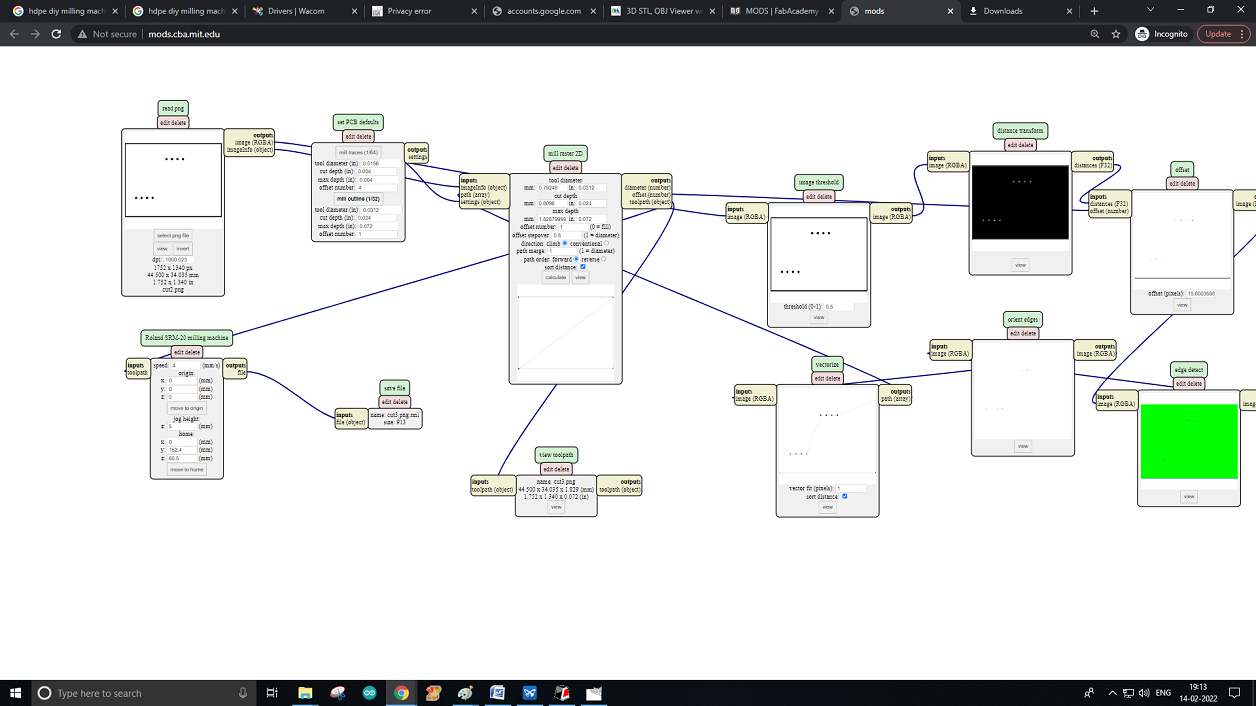
After that, I started printing of the board by setting the printer parameters |
|||||
 |
|||||
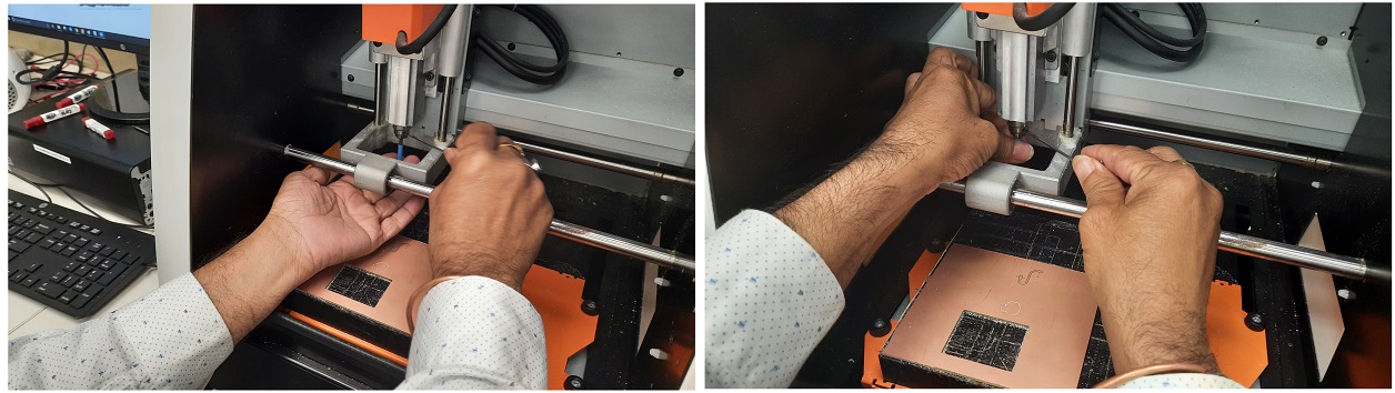
After downloading the .rml file to the local system, now I mounted the milling bit i.e 1/64 for trace and 1/32 for cut. During the installation of the milling bits we have to be careful by holding it in two finger else anything mishap may happen. |
|||||
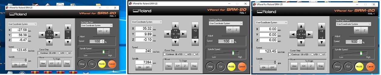
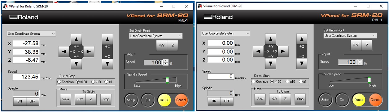
After that, I set to zero for x, y, and z for this Milling which will be a User-Friendly V-Panel. The SRM-20’s VPanel controller provides a simple interface for adjusting tool position and moving the cursor to set the milling starting point. The V-Panel also allows easy control of the feed rate and spindle speed with pause and resume operation, plus tracking of X,Y,Z axis milling with a numeric readout in millimeters or inches. |
|||||
 |
|||||
 |
|||||
 |
|||||
 |
|||||
 |
|||||
|
|||||
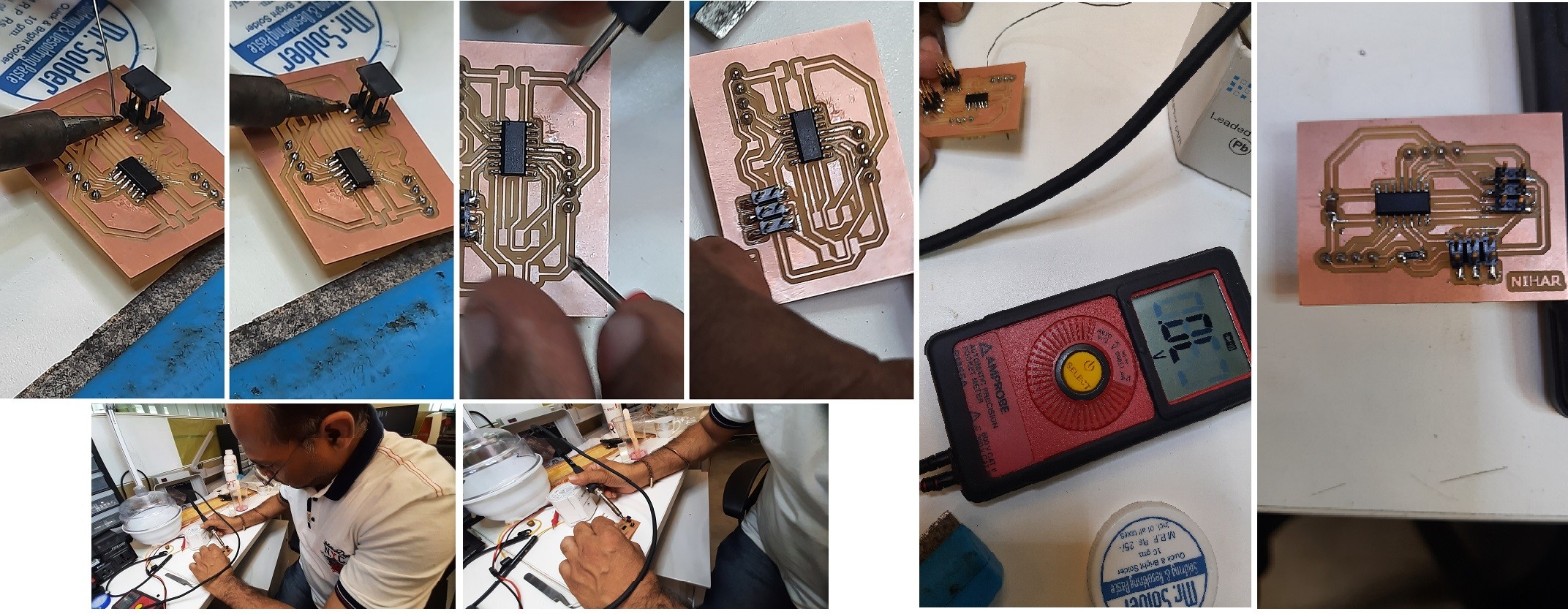
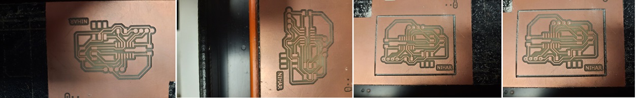
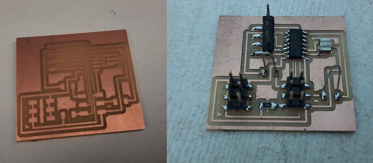
After milling, I carefully de-mounted the printed board from the milling bed and looks like this : |
|||||
 |
|||||
Soldering of Components to the board |
|||||
After successful milling of the board, I mounted the following components; |
|||||
ATTiny 44 - 1 no. Jumper (3x2) - 2 nos. Capacitor (22mf) -1 no. 10K Register - 1 no. |
|||||
|
|||||
|
|||||
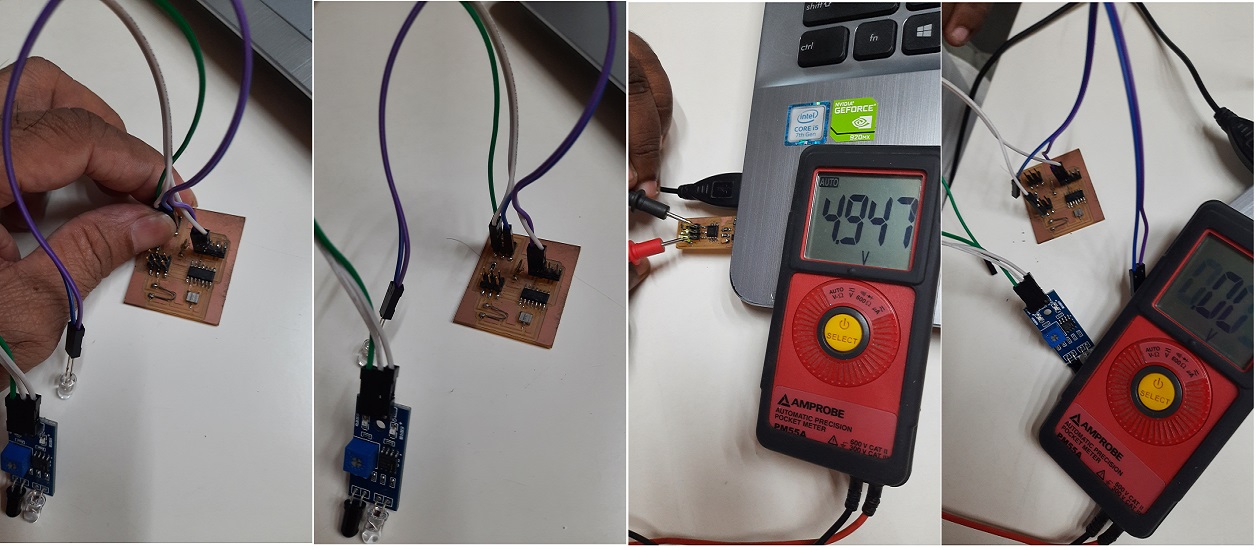
After moutning all the SMD components I tested the circuit so that I can go for testing, but unfortunately, I found some error in the board and its not passing the required power. I tried to find out the error and found that, there is some itching issue with the board for which the propoer power is not transmitting. |
|||||
Aagain I designed the file and milled another board, so that I can complete the task perfectly. |
|||||
 |
|||||
 |
|||||
 |
|||||
 |
|||||
 |
|||||
 |
|||||
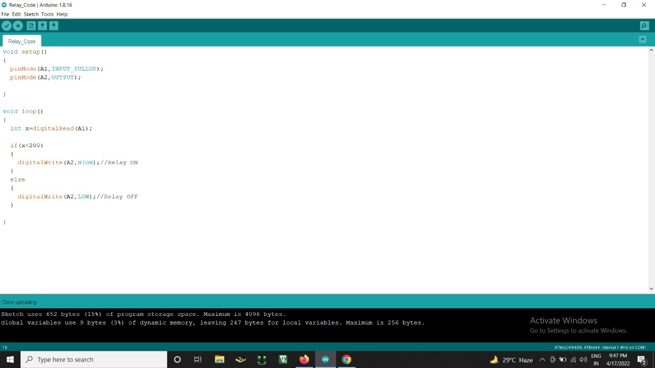
Code for running the application to see the result that whether working fine or not. |
|||||
 |
|||||
For the assignment, I tried to implement the power ON-Off with an IR sensor, which will sense by the motion. |
|||||
An infrared proximity sensor or IR Sensor is an electronic device which emits the infrared lights to sense some aspect in the surroundings and can be employed to detect the motion of an object. Since, this is a passive sensor, it can only measure infrared radiation. |
|||||
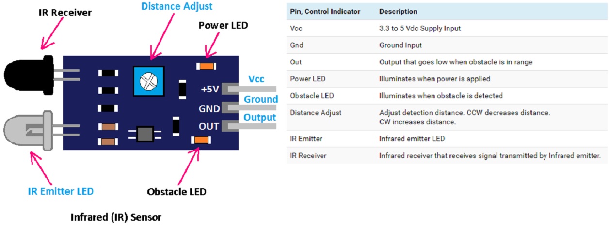
IR Sensor PinOut & descriptions |
|||||
 |
|||||
VCC is the power supply pin for the IR sensor which I connected to the 5V pin. |
|||||
How IR Motion Sensor Module Works |
|||||
The working of the IR sensor module is very simple, it consists of two main components: the first is the IR transmitter section and the second is the IR receiver section. In the transmitter section, IR led is used and in the receiver section, a photodiode is used to receive infrared signal and after some signal processing and conditioning, you will get the output. |
|||||
An IR proximity sensor works by applying a voltage to the on-board Infrared Light Emitting Diode, which in turn emits infrared light. This light propagates through the air and hits an object, after that the light gets reflected in the photodiode sensor. If the object is close, the reflected light will be stronger, if the object is far away, the reflected light will be weaker. If you look closely toward the module. When the sensor becomes active, it sends a corresponding Low signal through the output pin that can be sensed by an Arduino or any kind of microcontroller to execute a particular task. The one cool thing about this module is that it has two on-board LEDs built-in, one of which lights on when power is available and another one turns on when the circuit gets triggered. |
|||||
IR Motion Sensor Module – Parts |
|||||
This sensor has three pins two of which are power pins levelled VCC and GND and the other one is the sense/data pin which is shown in the diagram above. It has an on-board power LED and a signal LED the power LED turns on when power is applied to the board the signal LED turns on when the circuit is triggered. This also has a comparator Op-amp that is responsible for converting the incoming analogy signal from the photodiode to a digital signal. We also have a sensitivity adjustment potentiometer; with that, it can adjust the sensitivity of the device. Lastly, we have the photodiode and the IR emitting LED pair, which all together make the total IR Proximity Sensor Module. |
|||||
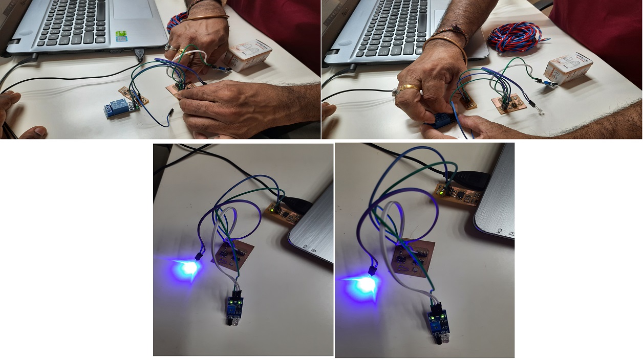
After that, I planned to make the connection for moving towards the final result. |
|||||
 |
|||||
 |
|||||
Video |
|||||